In the realm of construction, reaching great heights has always been a challenge. Whether it's towering skyscrapers or industrial facilities, accessing elevated areas safely and efficiently is crucial. That's where rope suspended platforms come into play, transforming how workers navigate heights with ease.
Solving High ChallengesPicture this a skyscraper looming above, its facade gleaming in the sunlight. How do workers reach those lofty heights to clean windows, conduct repairs, or perform maintenance tasks? Traditional methods like scaffolding or cranes have limitations, making them impractical for certain jobs. That's where rope suspended platforms step in, offering a versatile solution to these high challenges.
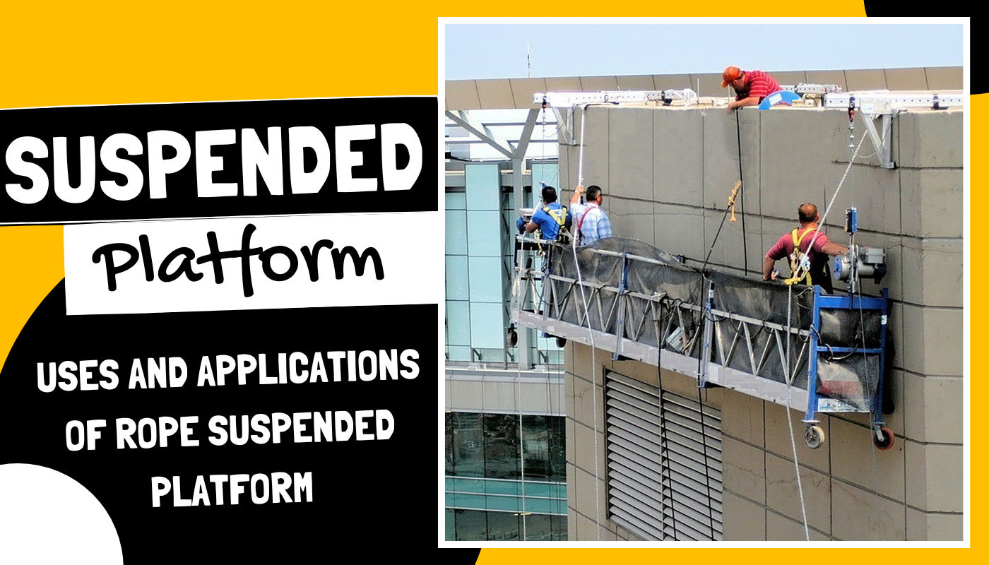
At its core, a rope suspended platform is a specialized piece of equipment designed for accessing high-rise structures and elevated areas. It consists of a sturdy platform equipped with guardrails, suspended from above by wire ropes or steel cables. This platform serves as a safe working surface for tasks such as construction, maintenance, and repairs, providing workers with the stability and security they need to perform their jobs efficiently.
Now, let's take a closer look at how these platforms operate. The process is remarkably simple yet highly effective. The platform is suspended from above using wire ropes or steel cables, carefully anchored to the building or structure at strategic points to ensure stability and weight distribution. Once assembled, the platform is lifted to the desired working height using hoists or winches, controlled by an operator via a control panel.
The key components of a rope suspended platform work together seamlessly to facilitate smooth vertical movement. From the suspension system to the safety devices and control panel, each element plays a crucial role in ensuring the safety and efficiency of the platform.
The suspension system, composed of wire ropes or steel cables, bears the weight of the platform and its occupants, providing the necessary support for vertical movement. Safety devices such as lifelines, emergency brakes, and anti-tilting mechanisms are in place to safeguard workers in case of unexpected incidents. Meanwhile, the control panel allows the operator to control the platform's movement with precision, ensuring smooth ascent and descent.
With its inner workings understood, let's explore the practical applications and functionality of rope suspended platforms across various industries.
Rope suspended platforms excel in tasks that require workers to access elevated areas safely and efficiently. Whether it's painting a building facade, repairing exterior surfaces, or installing facade elements, these platforms offer a stable and secure platform for workers to perform their duties with confidence.
Safety is paramount when working at heights, and rope suspended platforms are equipped with various safety features to minimize risks. From safety ropes and lifelines to emergency brakes and anti-tilting mechanisms, every precaution is taken to protect workers from falls and accidents.
The versatility of rope suspended platforms makes them indispensable across a wide range of industries.
In the construction industry, rope suspended platforms are used for tasks such as high-rise building maintenance, facade cleaning, and general construction work. In industrial settings, they are utilized for maintenance, cleaning, and installation suspended platform tasks, providing workers with safe and efficient access to elevated areas.
Real-world examples abound, showcasing the effectiveness of rope suspended platforms in various applications. From cleaning windows on skyscrapers to conducting maintenance on wind turbines, these platforms have become invaluable tools for workers operating at heights.
Operating and maintaining rope suspended platforms requires proper training, certification, and adherence to safety protocols.
Operators must undergo rigorous training to ensure they are proficient in operating the platform safely and efficiently. Certification programs provide them with the necessary skills and knowledge to handle the equipment with confidence.
Regular maintenance is essential to keep rope suspended platforms in optimal condition. This includes inspecting the equipment for signs of wear and tear, lubricating moving parts, and replacing worn-out components as needed. By following these maintenance tips, operators can ensure the platform operates smoothly and reliably.
When it comes to rope suspended platforms, quality is paramount. That's where Sona Construction comes in, offering top-quality solutions for better performance and longevity.
Sona Construction's rope suspended platforms are built to the highest standards, using premium materials and advanced engineering techniques. This ensures they deliver exceptional performance and reliability, even in the most demanding environments.
By investing in Sona Construction , customers can enjoy peace of mind knowing they're getting the best value for their money. These platforms are designed for longevity and efficiency, helping customers maximize their productivity and minimize downtime.
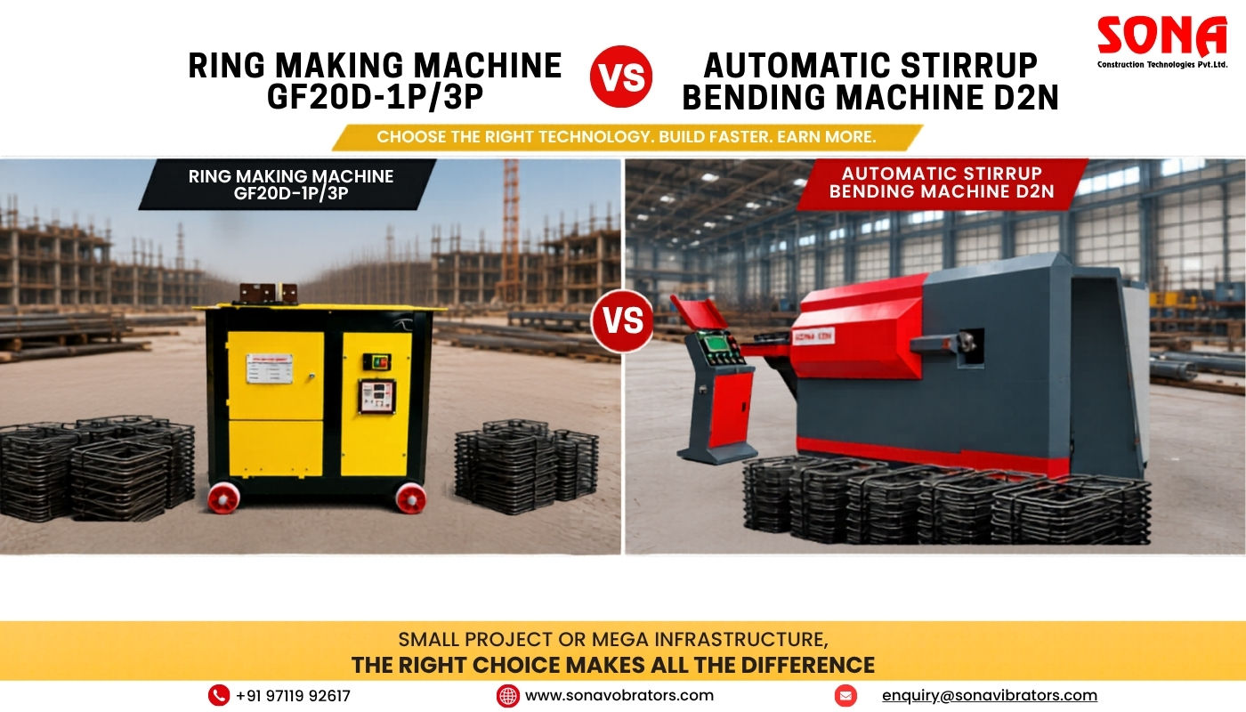
Ring Making Machine vs Automatic Stirrup Bending Machine: The Complete Guide to Maximising Rebar Production, Reducing Labour Costs & Increasing Profitability
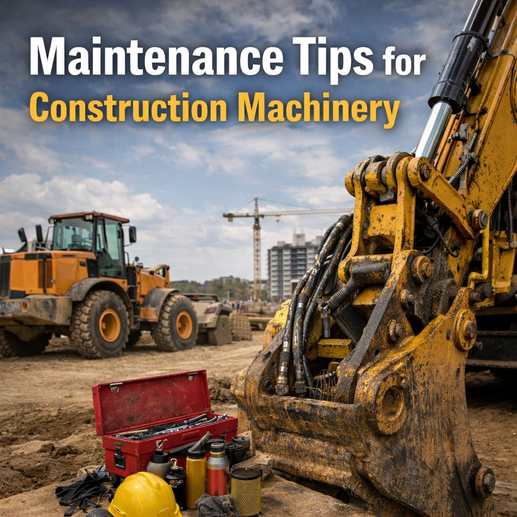
Maintenance Tips for Construction Machinery:The Complete 2026 Guide to Maximising Equipment Lifespan, Safety & Uptime
.png)
Cover Blocks in RCC – Importance, Correct Sizes & Critical Mistakes to Avoid

Mini Excavators vs Full-Size Excavators: Which One Do You Really Need?
.png)
Types of Foundation in Construction: Isolated, Raft & Pile Explained
Copyright © 2026 Sona Construction Technologies Private Limited