

Insert the tommy bars into the front base and rear base respectively. Adjust the height of the tommy bars and tighten the bolts to form the front base and rear base.
Lead the front and rear beams into sleeve on front or rear base, position the middle beam between the front and rear beams and tighten the bolts and nuts.
Mount the working wire rope and safety wire rope onto the coupling sleeve of the front beam. Make sure that the ends of the ropes must be clamped well, and then, put the stopper onto the safety wire rope at the proper position. ( Make sure that the ends of wire ropes must be Ferrules well, and then, put the clamps onto safety wire rope at proper position. )
Adjust the front beam overhang and fix the upper column with tommy bar with the bolts and make sure that it is not askew.
Adjust the distance between the front and rear bases. Adjust the three beams to make sure that the three beams should be in the same straight line. Care must be taken that the height different between the three beams must not larger than 10 cm. Moreover, it is only allowed that the front is higher than the rear.
Fix the coupling sleeve on the tommy bar of the rear base. Lead one end of the reinforced wire rope into the coupling sleeve of front beam and tighten the rope clamp. Lead the reinforced wire rope to the rope sheave on upper column and the other end through the hole of the close side of the turnbuckle, tighten the rope clamp. Adjust the screw bar of the turnbuckle and tighten the reinforced wire rope to raise one end of front beam about 3 cm.
Place the suspension mechanism to its working position with the reach of front hanger plate out of the working wall space about 60cm. The distance between two front hanger plates of suspension mechanism should be the same as the length of the Suspended platform.
Place the counter weight onto the poles of the rear holder and fix them with bolts and slowly release the wire ropes.
The installation ground must be horizontal. The place where is sloped shall be leveled up by wood plate; if the installation surface is water-proof and heat insulated, it must place the wood plate with thickness of 2.5~3.0cm beneath the front and rear base to prevent it from being damaged.
Adjust the height of the front adjusting stand of the suspension bracket and make the bottom side of the front beam higher than the parapet wall (or other barriers).
The rated adjusting range of the protrusion at the front beam is 0.3~1.5m. If it exceeds the rated protrusion length, it must take reliable measures and reduce the rated working load, and then be allowed to use after the department in charge consents.
Under the allowable condition, the distance between the front and rear base must be kept maximal as much as possible.
The distance between two brackets must be adjusted to the one that distance between the protruding ends of the front beam is more 3~5cm than the length of the suspension platform.
When tightening the reinforced wire rope, it must keep the front beam turned up 3~5cm, which will then produce prestressing and improve the rigidity of the front beam.
When installing the wire rope, the quantity of the rope clamp must not be less than 3 pieces, and the U-shape opening is designed at the side of the tail end of the wire rope, keeping same direction. The rope clamp must clamp the hoisting points in turns. When the nut of the rope clamp is tightened, it must keep the clamp of the wire rope at 1/2~1/3 diameter.
When placing the wire rope vertically, it must coil and place the wire rope on the floor, with one end to be fixed on the top end of the suspension protrusion of the suspension mechanism, the other end to be placed downward slowly along the wall after it comes out. It is prohibited to throw the wire rope in coil. After the wire rope is released completely, it must separate and hold the rope knot carefully; the excessive wire rope on the ground must be coiled and bound carefully. It is not allowed to place on the ground untied
Each clump weight is 25kgs; When loading the clump weight, it must follow up for the two kinds of the suspended access equipment respectively. No modification is allowed to make freely.


The quantity of counter weight is subject to the table 2-1 and 2-2. After the quantity of the counter weight is defined, it can place the counter weight symmetrically on the 4 installation posts at the rear base.
| Extension length of the front beam a (mm) | Maximal working load W2(kg) | Distance between the front and rear bracket b(mm)
|
Loading counter weight
|
||||||
|---|---|---|---|---|---|---|---|---|---|
| 700 | 800 | ≥2000 | ≥2200 | 1250 | 50 | ||||
| 900 | 800 | ≥2600 | ≥2800 | 1000 | 40 | ||||
| 1100 | 800 | ≥3000 | ≥3200 | 1100 | 44 | ||||
| 1300 | 800 | 4000 | 4000 | 1200 | 48 | ||||
| 1500 | 600 | ≥3800 | ≥3800 | 1200 | 48 | ||||
| 1700 | 500 | ≥3600 | - | 1250 | 50 | ||||
The suspension platform must be installed at the wall approaching to the ground of the suspension mechanism on the top.
Installation sequence

The safety lock and the hoists should be installed respectively at the safety lock’s bracket and hoists’ support of the erection frame of the hoists at both ends of the suspension platform.
When installing the safety lock, it must keep the scroll wheel of swing arm toward the inner side of the platform.

The hoists is installed inside the suspension platform. When making the installation, it must move the hoists into the suspension platform, keeping the dented rectangular frame at the back the hoists aiming to the support of the hoists, and then insert the pin roll, lock by the pin lock; afterwards, fix the hoists onto the horizontal pole of installation frame. Alternatively, it can also put the working wire rope into the hoists, and jog the ascending button to lift the hoists into the suspension platform for installation. If the latter method is used, it must level up the rope outlet of the hoists to empty, and then draw the wire rope off from the outlet carefully by hand so as to prevent the rope head from impacting the ground.
The electrical box is installed on the rear (high) balustrade in the middle of the suspension platform, with the door of electrical box towards its inner side. Two lifting pieces are used to fix the electrical box onto the handrail of the column plate.
After the electrical box is installed and fixed well, it must place the plug-in unit of the power cable, motor cable and control switch cable into the corresponding socket beneath. When inserting the plug-in unit into the socket, it must aim to the location of base pin, and then push with average force. No sharp force or violent operation is allowed; otherwise it will damage the plug-in unit. All plug-in units said above are not allowed to operate when power supply is switched on.

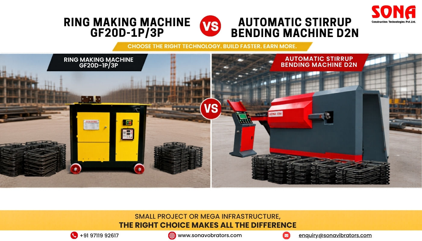
Ring Making Machine vs Automatic Stirrup Bending Machine: The Complete Guide to Maximising Rebar Production, Reducing Labour Costs & Increasing Profitability

Maintenance Tips for Construction Machinery:The Complete 2026 Guide to Maximising Equipment Lifespan, Safety & Uptime
.png)
Cover Blocks in RCC – Importance, Correct Sizes & Critical Mistakes to Avoid

Mini Excavators vs Full-Size Excavators: Which One Do You Really Need?
.png)
Types of Foundation in Construction: Isolated, Raft & Pile Explained
Copyright © 2026 Sona Construction Technologies Private Limited